Form-In-Place Gaskets vs Die-Cut Gaskets
Why choose one over the other?
When beginning your project it is important to know the differences between FIP and Die Cut. The nuances between the processes often lead to a larger discussion of variables and trade-offs. Each choice will be uniquely based on the needs of a specific project and the stage of completion in a design’s life cycle. The best choice often evolves as the product moves from design to prototype, scale up, production, and possibly contract manufacturing. The following is a list of some of the key variables to consider for these two gasket process options. The order of priority will vary based on the customers needs at that time.

10 Considerations:
For more information, please see the KraFAB pages for Form-In-Place (FIP) and Die Cut services for reference
Both processes can be used for general sealing using FIP or sheetstock materials that are electrically insulating for environmental gaskets or electrically conductive for Electromagnetic Interference (EMI) shielding gaskets. For EMI gaskets, whether made using the FIP or Die Cut process, electrically conductive silicones are often the material of choice.
Form-In-Place (FIP) vs Die Cut Elastomer Gaskets
Using this list of variables, we can detail some of the differences between the two as a starting point to evaluate which fits your needs for a given project and stage in the product life cycle.
To further delve into the details and take advantage of our decades of experience, please contact KraFAB.
1. Gasket Material
The base material used to make elastomer gaskets starts as a liquid polymer. Fillers are added to give it the desired final properties when it is cured. There are many cure in place systems and filler options. For die cut gaskets, the bulk material is formed into sheet gaskets or roll and cured in a casting, molding or extrusion process. The cure process may not be important to the customer, but the physical and electrical properties of the bulk sheet usually are.
The properties include but are not limited to hardness (durometer), operating temperature range, compression set, electrical conductivity, electrical insulation, outgassing, tensile strength, elongation percentage, tear strength, compression/deflection, thermal conductivity, shielding effectiveness, fluid resistance and flammability rating. These properties also apply to materials used in Form-In-Place (FIP), also referred to as Cure-In-Place, however the cure occurs after the material is dispensed on the customer’s part. Therefore FIP material selection criteria may also include the cure process. If the customer part will not tolerate the cure time and temperature of a heat cure FIP material, a room temperature cure (RTV) material can be selected.
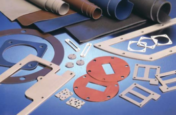
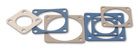
Die Cut Parts

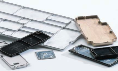
Parts with FIP gasket

2. Project Quantity
Many projects start with a few parts for design and prototype and then scale up to hundreds or thousands per month. Alternately we have had projects that required 5 parts of a very expensive material for the life of the program. Both the FIP or Die Cut process can be scaled to produce 1 or 1 million parts. One of the original applications for the FIP process for EMI shielding was the housing for cellular phones. A very high volume process involving automated application of a dispensed heat cured in place electrically conductive silicone EMI gasket, dozens of multihead dispensing gantries synchronized with inline curing ovens that yielded a fully cured EMI gasket on the phone housing that held the electronics.
Die cut gaskets can be cut one at a time using a steel rule die and a vertical press. They can be scaled up by designing multi cavity tools and moving to a rotary cutting process for materials that are available in a roll format as compared with sheets.
In general the process choice is not often determined by the initial or production volume. The other factors tend to have a bigger impact on that decision. It is however important to know the projected quantity demand for the part and timeline as that impacts many of the other variables including lead time, tooling, material format and supply chain.
3. Tooling
Both the FIP and Die Cut process involve some level of tooling.
For the FIP process, each part that the gasket is applied to must be held in a fixed position so the dispensing process places the gasket accurately. Initial FIP tooling may be built without custom machining if the housing shape allows. As an example, a five sided box that is flat on the back and has two sides that are square makes it amenable to fixturing without custom machining. As parts become more complex, custom fixtures, also referred to as pallets, are built to hold one or many parts. Tooling can be machined from aluminum or reinforced plastics.
The pallet material and quantity of pallets depending on the housing production demand rate and the cure system chosen, room temperature cure (RTV) versus heat cure FIP. For low volumes using an RTV FIP material, a single custom machined pallet designed using the CAD file for the customer part and machined from an engineered plastic may be sufficient. For a high volume part where a heat cured material is desired, multiple machined aluminum pallets may be the best choice. For die cut parts, whether for vertical press or rotary process, the tool cuts the part shape from the base material. The amount of time and money investment in the tooling is a function of the part complexity and the planned quantity. For die cut gaskets a change in the gasket shape requires a change in the tool. In contrast, for FIP gaskets if the locating dimensions used to position the part on the tool (pallet) do not change, the gasket path can be changed without the need to change the tooling. The dispensing head is programmed to a new path to yield the required gasket placement.
4. Lead Time
The lead time for the various components of the customer parts is generally understood and tracked. For die cut gaskets the material, tooling and cutting lead times are key. The die cut gaskets can be made independent of the other parts in the assembly. They can be supplied and inventoried in quantities and timed so they do not impact the production schedule of the customer assembly. FIP gaskets are dispensed on customers’ parts. Therefore the shields, covers, enclosures or housings and the material to be dispensed have to be at the dispensing location before the process starts. The material to be dispensed, since it is not yet cured, has a shelf life. Therefore timing delivery of the material and parts that require a gasket to the dispensing location is very important to lead time management. The finished FIP gaskets are inventoried on the part.
5. Thickness Tolerances
The finished gasket dimensions for a die cut gasket are determined by the material thickness of the bulk material and the dimensions of the tool used to cut the gasket shape. The thickness tolerances are part of the bulk material description. The tolerances of the tool used to cut the gaskets can vary with the type of tool used. Steel rule dies are commonly used for cutting gaskets. If tighter tolerances are required, machined tools can be produced. The cutting edge of the tool defines the outside dimensions of the gasket shape. For the FIP process, holding each part in the same position for each part dispensed is critical. The dispensing head is driven by computer code based on the CAD File for the customers part. The location of the gasket is keyed on a centerline of the gasket. The start and stop zone of the dispensed gasket has a known tolerance range. The width and height of the finished gasket is impacted by the thixotropic nature of the material dispensed as well as the size of the needle it is dispensed with and its speed of travel along the path of the centerline. Often the gasket thickness is determined by the tolerance stack up of all the components in the cross section of the assembly.
For EMI Shielding Gaskets, there is also a range of compression between the gasketed surfaces required to get optimal conductivity and shielding.
6. Closure Force
In general the amount of force required to get optimal sealing performance from the gasket is determined by the gasket material properties and shape. You can choose the material properties within a range for both die cut and FIP processes. Die cut bulk materials are generally flat sheets so the cross section is square or rectangular at any given point. The FIP process dispenses a thixotropic material that settles into a shape.. The shape can be influenced by the material formulation, the dispensing process and post dispensing processes.
The amount of closure force required to get the gasket to properly seal will impact the method and location of fasteners used on the enclosure assembly.
7. Real Estate
In this discussion, real estate refers to the room we have for a gasket. Simple perimeter gaskets are easily die cut or dispensed. At the other extreme, we have seen customer parts that have a fixed external form factor and dimensions that have increased demand for space internally leading to a more complex gasket design with a smaller area for its location. The die cut tools have a practical limitation to how narrow and complex a gasket they can produce. Placing small complex gasket shapes in tight spaces is one of the key advantages of the FIP process. This includes being placed on slopes and steps and varied thickness.
8. Revisions
A change in a die cut gasket is a change in the die cut tool with the applicable price and lead time. For prototype and low volume gaskets, computer controlled CNC knife cutting is an option.
For the FIP elastomer gasket process, a revision change in the gasket location or cross section is achieved by a change in programing or other dispensing process changes. The Form-In-Place (FIP) gasket process is ideal for making adjustments or changes during design, prototype and scale up product life cycle stages. Additionally, since kraFAB has a broad customer base and experience, we often have a variety of materials on hand and on order to allow alternate material choices to customers without long lead times.
9. Installation
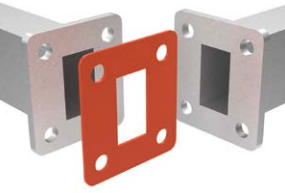
Die cut solid gaskets must be installed.
Form in place liquid gaskets are dispensed and cured on the customer part, either at room temperature (RTV) or heat cured in an oven. They are an installed gasket solution.
Both gaskets must be packaged and handled properly to prevent damage during transportation and installation.
10. Supply Chain
Supply chain management to meet on time delivery and quality requirements is a continuous challenge. Die cut gaskets can be produced and inventoried independent of the other components usually where the assembly occurs. For the FIP process, the gasket inventory is on the part (housing, enclosure, cover, shield). There is a coordination needed between the supplier of the shields, covers, enclosures or housings and the dispensing operation. This is where our decades of experience in supply chain management pays off.


Form in place gaskets vs die cut gaskets conclusion:
As you have read, the discussion of FIP Gaskets vs Die Cut Elastomer Gaskets is a complicated choice. Whether physical and electrical properties of the material are important for a design or a quantity demand for a specific part is concerned or flexibility in a project as the design evolves is important–these conditions and more are all important for consideration before production. All these reasons and more is why it is advantageous to work with KraFAB. Reach out to KraFAB, our engineers will help you choose what EMI shielding process is best for your design and optimize a production line to fit your timeline. Our facility scales for each project so if you need one part or one hundred million parts we are suited to address your design’s specific needs.
While it is ideal to pick a gasket material and process at the initial design stage, we have helped more than a few customers design and implement an elastomer gasket solution later in the product life cycle.
Contact KraFAB to discuss your specific project and its requirements.
